

Starlink’s Gen2 isn’t just a new shape — its rectangular phased array, denser RF elements, and motorized tilt measurably improve coverage and throughput.
You’ll see steadier links during satellite handoffs, better service at high latitudes, and download speeds typically between 25 and 220 Mbps depending on model and conditions.
This post breaks down how the antenna and firmware changes deliver those gains, what limits uplink and downlink in the real world, and which Gen2 models make sense for homes, boats, and enterprise.
Immediate Breakdown of Starlink Gen2 Antenna Upgrades for Coverage and Throughput

Starlink’s Gen2 terminal swapped the round dish for a rectangular phased array with built-in motors. Real improvement came from denser RF elements and better beamforming code that kept signal locks tighter during satellite handoffs and partial obstructions. Gen2 pulls between 25 and 220 Mbps down depending on which model you’re running, with upload sitting steady at 5 to 20 Mbps across the board. Coverage got better because the beam patterns tightened up, the phased array steered faster, and the motors let the dish track satellites across a wider slice of sky.
Throughput numbers jump around between Gen2 models because of antenna size, RF power, and what the thing’s built for. Standard Gen2 gives you 25 to 150 Mbps down, good enough for home use and lighter commercial setups. Performance Gen2 (they used to call it Flat High Performance) hits 25 to 220 Mbps and it’s designed for enterprise, boats, and mobile installs where you care more about keeping the link alive during movement and bad weather than hitting top speed. These ranges reflect actual congestion, time of day, how many gateways are nearby, and what’s blocking your view. Lab tests can push higher, but day to day you’ll land somewhere in these windows.
Gen2 firmware tweaks phase delays across antenna elements in real time, carving narrower beams that block interference and boost your signal-to-noise ratio. More elements in the phased array mean better effective aperture and directional gain without making the dish bigger. Motors tilt the dish to the right elevation and azimuth automatically, cutting down on setup mistakes and keeping alignment solid as the constellation moves overhead. Upgraded low-noise amps and power amps in the RF front end push higher EIRP, giving you a stronger uplink budget. Better heat management stops the RF output from throttling when traffic stays high or the temperature climbs. Improved satellite tracking in the firmware cuts the latency spike and throughput dip when you switch between satellites.
Gen2’s geographic footprint stretched past Gen1 by pairing the motorized dish with tighter constellation passes and better gateway backhaul. The phased array locks onto satellites earlier in their pass and holds the connection longer, so you get better service windows at high latitudes and in edge zones. Mechanical alignment keeps the array pointed close to optimal, compensating for installation errors and environmental shifts that would wreck a fixed-mount antenna’s performance.
Comparing Gen2 with Gen3: Gen3 hits higher peak throughput (up to 400 Mbps on Performance models, with spikes to 450), handles weather better through refined beamforming, and gives you a 110-degree electronic field of view. Gen3 ditched the motors entirely. You place it manually using app guidance, then pure electronic steering takes over. Fewer moving parts, but you need more precise initial setup. For raw speed and long-term durability, Gen3 wins. For off-grid power efficiency and proven field reliability, Gen2 still makes sense, especially after you mod it to 12V DC.
Technical Evolution of Gen2 Antenna Architecture and Phased‑Array Improvements
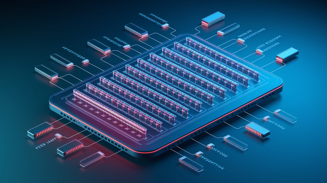
Starlink’s phased arrays replaced parabolic dishes with flat panels holding hundreds of small radiating elements, each with its own transmit/receive module. Electronic beam steering works by adjusting phase and amplitude at each element so constructive interference forms a narrow, directional beam aimed at a specific satellite, while destructive interference kills signals in other directions. Happens in microseconds, so the terminal tracks a moving satellite without physically rotating. Gen2 refined this by adding more active elements, upgrading RF chipsets, and optimizing element spacing to improve gain and steering versatility across Ku and Ka bands.
Gen2’s antenna design widened effective steering angles while keeping high gain at the beam peak. The element layout uses a denser grid with tighter spacing, which raises maximum usable frequency and improves sidelobe suppression. Less interference from adjacent beams and neighboring satellites. The RF front end in Gen2 includes lower-noise amps on receive and higher-output amps on transmit, directly increasing link budget so the terminal can close links in marginal conditions (heavy rain, low elevation angles, congested cells). Hardware improvements combine with firmware updates that dynamically adjust beamforming coefficients based on real-time signal quality, so the array continuously adapts to changing propagation.
Beamforming and Steering Efficiency
Beamforming shapes a narrow pencil beam with high directivity, concentrating radiated power in a small angular region and improving carrier-to-noise ratio at both the terminal and the satellite. Narrow beams enable spatial reuse. The same frequency can serve multiple users simultaneously as long as their beams point different directions, increasing per-beam capacity and overall network throughput. Critical when constellation density rises and more satellites are visible at once. The terminal can choose the least congested beam or switch mid-session to maintain throughput. Lower beamwidth also reduces latency variation during handoffs because the terminal can pre-lock the next satellite before releasing the current one, shortening the gap between connections.
The tradeoff between beamwidth, antenna gain, and steering versatility is fundamental. Narrower beams deliver higher gain and better interference rejection but require more precise pointing and faster tracking to follow a satellite across the sky. Wider beams are more forgiving during motion (vehicle, vessel) or partial obstructions (tree branches, building edges) but sacrifice peak throughput because radiated power spreads over a larger area. Gen2 balances this by combining motorized physical alignment (keeps the array’s boresight roughly on target) with electronic steering that fine-tunes the beam within a ±50 degree cone, delivering both high gain and enough angular flexibility to handle real-world installation imperfections and brief obstructions.
Starlink Gen2 vs Gen3 Coverage Footprint Changes and RF Performance
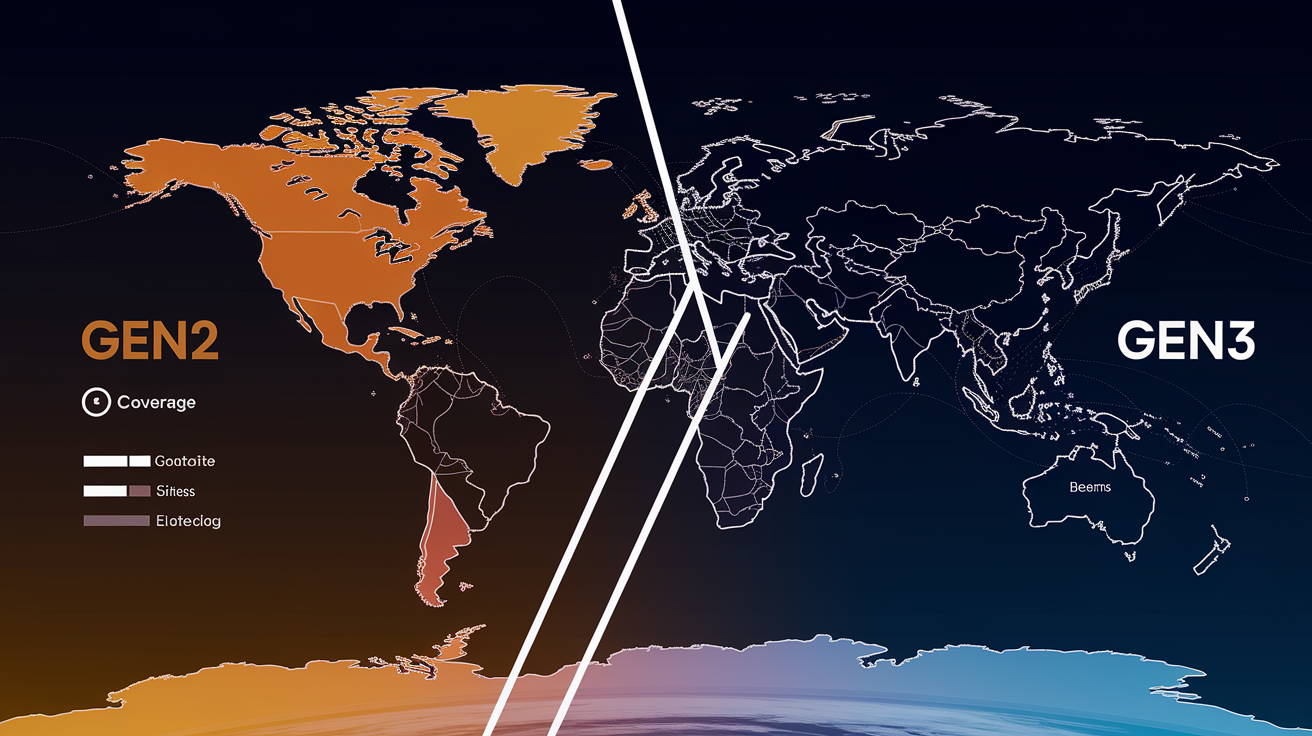
Gen2 antenna architecture improved geographic coverage reliability by pairing motorized alignment with the growing Starlink constellation density, so terminals could lock onto satellites earlier in each pass and maintain connections at lower elevation angles than Gen1. The rectangular phased array in Gen2 offers a wider effective field of view than the round Gen1 dish when combined with motor-driven tilt adjustments, letting the terminal serve users closer to the horizon in high-latitude regions or areas with sparse satellite coverage. As SpaceX deployed additional orbital shells and increased satellite count per plane, Gen2 terminals benefited immediately because the hardware could dynamically select the best-signal satellite from multiple visible options, reducing the impact of congestion on any single beam.
Regional capacity (determined by gateway backhaul bandwidth, number of ground stations within range, and user density per cell) directly influences how consistently a terminal hits its rated throughput. Gen2 improved over Gen1 in practice because the higher element count and better RF front end allowed the terminal to close links with satellites at greater slant ranges, effectively expanding the geographic footprint served by each gateway. In loaded cells where user demand exceeds available beam capacity, Gen2’s improved beamforming helps by reducing co-channel interference and enabling tighter frequency reuse, which increases the number of concurrent users a single satellite can serve. Gen2 users experience fewer slowdowns during peak hours compared to Gen1, even when constellation density is identical.
More satellites in view means Gen2 can choose less congested beams and switch satellites proactively before signal quality degrades. Upgraded ground stations with higher fiber capacity reduce bottlenecks, allowing Gen2 terminals to fully utilize their improved RF link budget. Wider electronic steering range in Gen2 extends the usable arc of each satellite pass, increasing total airtime per satellite and improving coverage at the edges of cells. Higher antenna gain and better low-noise amps in Gen2 mean weaker satellite signals still close the link, expanding effective coverage into fringe zones. Gen1 and Gen2 routers covered roughly 2,000 square feet indoors, limiting practical service footprint. Gen3 routers expanded this to approximately 3,200 square feet, reducing dead zones and improving overall user experience even when the satellite link remains constant.
Throughput Benchmarks for Gen2 Antennas and Real‑World Performance Scenarios

Expected Gen2 throughput ranges depend heavily on terminal model and deployment context. Standard Gen2 residential terminals typically deliver 25 to 150 Mbps download and 5 to 20 Mbps upload during normal operations. Lower end reflects congested evening hours in dense suburban cells, upper end represents rural off-peak performance. Performance Gen2 (Flat High Performance) and Enterprise V4 terminals push 25 to 220 Mbps download under similar conditions, benefiting from larger antenna apertures and higher transmit power that improve link margins in challenging environments (maritime installations, moving vehicles, locations with frequent partial obstructions). Upload speeds remain tightly clustered at 5 to 20 Mbps across all Gen2 models because uplink capacity is limited by terminal transmit power, regulatory EIRP caps, and satellite receiver sensitivity, not by the user terminal’s antenna design.
Uplink performance varies with congestion because each satellite beam allocates uplink slots to multiple users in a time-division or code-division scheme. When more terminals share a beam, each gets fewer uplink opportunities per second, reducing effective upload throughput even if the RF link budget remains strong. Multi-user load impacts download throughput similarly: satellite downlink beams use frequency reuse and spatial multiplexing, but total capacity per beam is finite, so adding users forces the scheduler to divide available time-frequency resources more thinly. Gen2 terminals handle this better than Gen1 by maintaining cleaner uplink signals (better sidelobe suppression reduces interference into adjacent beams) and by supporting faster beam-switching when the network controller redirects traffic to less-loaded satellites.
Environmental impacts (especially rain fade) affect Gen2 throughput predictably. Heavy rain absorbs and scatters Ku and Ka signals, weakening both uplink and downlink and forcing the modem to fall back to more robust (but slower) modulation schemes to maintain the connection. Scraped data indicates Gen3 terminals show 10 to 20% higher stability during rain and snow compared to Gen2, reflecting improved beamforming algorithms and better thermal regulation that prevent the RF front end from throttling under wet conditions. Gen2 users can expect download speeds to drop 20 to 40% during intense precipitation, with recovery happening within minutes once the rain cell passes, whereas Gen3 maintains closer to baseline performance throughout the event.
| Model | Downlink (Mbps) | Uplink (Mbps) | Notes |
|---|---|---|---|
| Gen1 (Round Dish) | 50–150 | 5–20 | Motorized; limited element count; Wi‑Fi 5 router |
| Gen2 Standard | 25–150 | 5–20 | Rectangular; motorized; proprietary cabling |
| Gen2 Performance (Flat HP) | 25–220 | 5–20 | Enterprise/maritime; wedge design for motion stability |
| Gen3 Standard | 25–150 | 5–20 | Motorless; 110° FOV; Wi‑Fi 6 router; RJ45 connectors |
| Gen3 Performance | up to 400 (450 peak) | 5–20 | Powder-coated aluminum; Advanced Power Supply; extreme weather rated |
Use wired Ethernet. Wi‑Fi adds latency and reduces effective throughput. Connect directly to the router’s Ethernet port for accurate speed tests and best performance. Test during off-peak hours. Early morning or mid-afternoon measurements avoid evening congestion, revealing the terminal’s maximum capability rather than network load limits. Run multiple trials. Single tests can catch transient satellite handoffs or brief rain fade. Average three to five consecutive runs for stable results. Choose nearby test servers. Selecting a speed-test server within 500 km reduces internet routing delays, isolating the Starlink link’s true throughput from backbone congestion.
Frequency Bands, Link Budget, and RF Power Characteristics of Gen2 Antennas
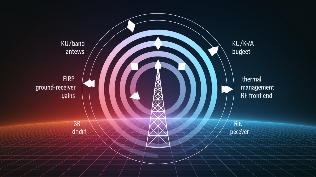
Link budget calculations sum the gains and losses between the satellite transmitter and the user terminal receiver (or vice versa on the uplink), determining whether the signal-to-noise ratio is high enough to close the link at a given data rate. EIRP (Effective Isotropic Radiated Power) measures the terminal’s transmit power multiplied by its antenna gain in the direction of the satellite. Higher EIRP improves uplink margin, enabling higher-order modulation (more bits per symbol) and faster upload speeds. Thermal performance matters because RF power amplifiers generate heat, and if the terminal can’t dissipate that heat, the firmware throttles transmit power to prevent component damage, directly cutting EIRP and reducing both uplink throughput and the ability to maintain a connection during marginal conditions like heavy rain or low satellite elevation.
Gen2 and Gen3 differ in power and thermal design. Gen2 terminals can be modified to run directly on 12V DC with power draw as low as 30 watts after removing or bypassing the internal AC-to-DC converter, making them attractive for RV, marine, and off-grid solar installations where every watt counts. Gen3 terminals use more efficient RF chipsets and improved thermal shielding, reducing overall power consumption under load and maintaining stable output power across a wider ambient temperature range, but the stock Gen3 configuration requires the included AC/DC power supply and doesn’t support simple 12V DC modification. For users prioritizing energy efficiency over peak throughput, modified Gen2 hardware remains competitive, especially when paired with battery banks or small solar arrays.
Power Draw and Efficiency
Gen2’s 12V DC modification involves replacing the factory power supply with a direct 12V input to the internal DC bus, bypassing the AC rectifier and reducing conversion losses. Field measurements show modified Gen2 terminals drawing approximately 30 watts during idle (dish aligned, no active data transfer) and 35 to 50 watts under sustained download load, compared to 50 to 75 watts for stock Gen2 and Gen3 configurations running through their AC supplies. Lower power draw extends runtime on battery systems. 30 watts continuous equals 720 watt-hours per day, fitting comfortably within a 200Ah 12V lithium battery bank and a modest 100-watt solar panel in sunny climates. This makes Gen2 the preferred choice for extended off-grid installations where replacing or upgrading to Gen3 would require larger power infrastructure, offsetting any throughput or durability gains.
Installation, Alignment, and Optimization Strategies for Gen2 Throughput and Coverage
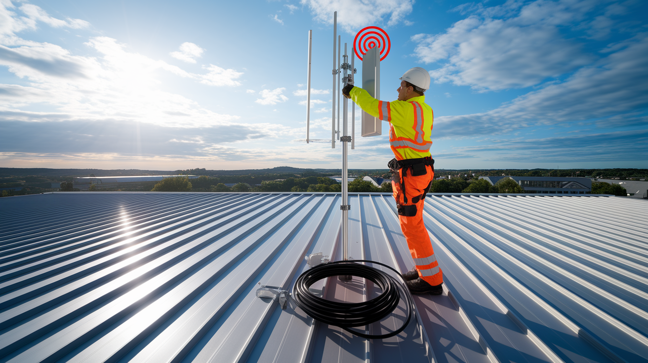
Motorized automatic alignment in Gen1 and Gen2 terminals simplifies installation by scanning the sky and adjusting dish tilt until the phased array locks onto a satellite, then continuously tweaking the motor position to track the constellation as it moves. This automation improves both coverage stability and throughput because the dish remains optimally pointed even as installation settling, thermal expansion, or wind shifts the mount slightly over time. Manual Gen3 setups require users to position the dish using app-guided feedback (a colored obstruction map and signal-strength meter), but once placed, the 110-degree electronic field of view handles satellite tracking without moving parts. For Gen2, motorized alignment means installation tolerance is higher. Small errors in mount angle or surface levelness are corrected automatically, whereas Gen3 punishes poor initial placement with degraded throughput and more frequent beam switches.
Mount rigidity and elevation angle relative to constellation geometry directly affect Gen2 performance. A loose or flexing mount lets wind vibration move the dish a few degrees, breaking the motor’s alignment loop and causing brief dropouts during gusts. Corrosion-resistant materials (marine-grade aluminum or 316 stainless steel) are essential in coastal or high-humidity environments because rust and galvanic corrosion weaken fasteners, allowing the mount to sag or twist under the dish’s weight. Elevation angle matters because Starlink’s polar and inclined orbital shells pass overhead at different inclinations. Mid-latitude users (35 to 50° N/S) see satellites across a wide swath of sky, but high-latitude users (above 55°) need the dish aimed closer to the horizon to catch satellites in inclined shells, increasing the chance of terrain or foliage obstructions. Gen2’s motors compensate by tilting the dish dynamically, but starting with the mount at the correct general elevation reduces motor runtime and mechanical wear.
Optimizing Gen2 in complex environments (urban canyons with tall buildings, dense forests, mountainous terrain) requires balancing obstruction avoidance with elevation angle. In urban canyons, mounting the dish on the highest accessible point (roof edge, pole above the roofline) and tilting it away from nearby structures improves line-of-sight to satellites at mid-to-high elevation, where the constellation is denser and beam handoffs happen faster. In rural areas with dense tree cover, pruning or removing a narrow cone of branches directly above the dish often delivers more throughput gain than relocating the entire installation, because Starlink satellites spend most of their pass time within a 40 to 60 degree arc centered on the dish’s boresight.
Use Ethernet directly. Bypass Wi‑Fi for speed tests and latency-sensitive applications. Gen2 requires a separate Ethernet adapter, but the wired connection eliminates wireless interference and jitter. Clear obstructions within the app’s red zones. The Starlink app overlays a real-time obstruction map. Removing trees, trimming branches, or relocating objects that fall into red areas immediately improves uptime and average throughput. Set the dish at the recommended tilt. The app provides an optimal tilt angle based on your latitude. Starting close to this reduces motor hunting and speeds up initial satellite acquisition. Secure the mount against movement. Tighten all fasteners, use lock washers, and consider guy wires or bracing for pole mounts taller than 1.5 meters to prevent wind-induced sway. Avoid thermal throttling. Ensure adequate airflow around the dish and power supply. Mounting in direct sun on metal surfaces can raise temperatures above the thermal throttle threshold, cutting transmit power and throughput by 20 to 30%.
Weather Resilience, Environmental Impacts, and Throughput Stability on Gen2 Hardware

Rain fade occurs when water droplets absorb and scatter Ku and Ka radio waves, weakening the signal traveling between the satellite and the terminal. The effect scales with rain rate: light drizzle (under 5 mm/hour) causes negligible attenuation, moderate rain (10 to 20 mm/hour) drops throughput by 15 to 25%, and heavy downpours (above 30 mm/hour) can reduce speeds by 40% or force the modem to fall back to the most robust modulation, cutting throughput in half. Signal absorption is frequency-dependent. Higher Ka-band frequencies suffer more than lower Ku-band, but Starlink uses both bands dynamically, so the terminal switches to the less-affected band when possible. Gen2 performance drops more noticeably during weather events than Gen3 because Gen2’s beamforming firmware and thermal regulation are less advanced, meaning the terminal can’t maintain peak transmit power or adapt beam patterns as aggressively when rain degrades the link.
Gen3 provides higher stability in rain and snow through improved antenna design: tighter element spacing and better RF front-end chips deliver cleaner uplink signals that penetrate weather cells more effectively, and enhanced thermal shielding prevents the power amplifiers from throttling when wet conditions cool the dish unevenly. Scraped data indicates Gen3 users report 10 to 20% higher throughput during storms compared to Gen2 users in the same cells, reflecting both hardware and firmware improvements. Gen2 remains functional during heavy weather but users should expect download speeds to sag into the 15 to 50 Mbps range during intense rain, recovering to normal within minutes once the storm cell passes. Snow accumulation affects Gen2 less than rain fade because the dish includes a heater that melts snow buildup automatically, but wet, heavy snow can temporarily block the signal until the heater clears the surface.
Rain intensity: attenuation scales with rain rate. Brief heavy showers cause steeper drops than steady light rain of the same total accumulation. Snow accumulation: wet snow sticks to the dish and blocks the signal until the heater melts it. Dry, powdery snow typically blows off or melts quickly, causing minimal disruption. Thermal load and throttling: high ambient temperatures (above 40°C / 104°F) or direct sun on a poorly ventilated mount can push the RF amplifiers into thermal protection mode, cutting transmit power and reducing uplink throughput by 20 to 30% until the dish cools.
Compatibility, Upgrade Path, and When Gen2 Users Should Consider Moving to Gen3
Gen2 and Gen3 hardware use incompatible cabling and connectors. Gen2 relies on proprietary cables with a rectangular push-lock connector, while Gen3 Standard models switch to industry-standard RJ45 Ethernet (supporting Power over Ethernet Plus on the dish end) and Gen3 Performance kits use a new 10-pin connector designed for higher power and marine environments. Gen2 routers output Wi‑Fi 5 and lack built-in Ethernet ports (requiring a separate adapter), whereas Gen3 routers include Wi‑Fi 6, dual-band mesh support, and two integrated Ethernet LAN ports. This means retrofitting a Gen2 installation to Gen3 typically requires replacing the cable run, upgrading the router, and in some cases installing new mount hardware because Gen3 dishes use a different base plate and attachment system.
Upgrading from Gen2 to Gen3 delivers measurable benefits in three areas: throughput (Gen3 Performance reaches 400 Mbps vs Gen2 Performance’s 220 Mbps ceiling), coverage (Gen3 router spans approximately 3,200 square feet vs 2,000 for Gen2, reducing Wi‑Fi dead zones), and durability (Gen3’s improved thermal shielding, IP67 rating, and corrosion-resistant materials extend service life in harsh coastal, desert, or high-UV environments). The cost difference (Gen3 Performance kits start around $2,000 USD compared to Gen2’s lower entry price) means the return on investment depends on whether those improvements directly address a current limitation. For users satisfied with 100+ Mbps speeds, adequate Wi‑Fi range, and stable performance in moderate climates, Gen2 remains capable and upgrading is optional.
Upgrade Triggers
Upgrading to Gen3 makes sense when Gen2 hardware fails and replacement parts are unavailable or expensive, since Starlink is phasing out Gen2-specific accessories and focusing support on Gen3. Users who need better indoor Wi‑Fi coverage (large homes, multi-story buildings, layouts with thick walls) benefit immediately from the Gen3 router’s 60% increase in effective range and Wi‑Fi 6’s improved multi-device handling. Installations requiring built-in Ethernet ports for wired devices (desktop workstations, security cameras, network-attached storage) avoid the hassle and cost of Gen2’s separate Ethernet adapter by moving to Gen3. Harsh environments (saltwater spray, extreme heat or cold, high winds, prolonged direct sun) favor Gen3’s powder-coated aluminum enclosure and upgraded sealing, which reduce corrosion and extend mean time between failures compared to Gen2’s less ruggedized construction.
Final Words
Gen2’s motorized rectangular dish and denser phased array sharpen beams and steering, improving coverage reliability and per‑user capacity over Gen1.
Real‑world downlinks span roughly 25–220 Mbps (uploads about 5–20 Mbps); model choice, congestion, and weather explain most variation.
It’s a practical midstep: alignment automation and lower‑power options (can run ~30W on 12V) help real installs, while Gen3 still leads on peak speed and durability.
Starlink Gen2 antenna upgrades coverage and throughput explained — they make everyday reliability better now and leave a clear path to Gen3 when you need more.
FAQ
Q: What is the throughput of Starlink Gen 2 and the Starlink antenna?
A: The throughput of Starlink Gen 2 antennas typically ranges from about 25–220 Mbps downlink and 5–20 Mbps uplink; newer Gen3 kits can reach 25–150 Mbps (standard) up to 400–450 Mbps (performance), depending on model and conditions.
Q: What is the Starlink 2 month rule?
A: The “Starlink 2 month rule” is not a published policy; people usually mean trial/relocation or billing windows. Check your Starlink account or contact official support for exact trial, refund, or move terms.
Q: How to make Starlink signal stronger?
A: To make a Starlink signal stronger, improve line-of-sight to the sky, raise and secure the mount, remove nearby obstructions, use Ethernet, keep firmware updated, and minimize local RF interference or reflective surfaces.